Solid-State Transformers: How Semiconductor Switching Replaces Heavy Copper in Modern Grids
-
Posted in : Uncategorized:
- On : Oct 14, 2026
Rethinking Grid Architecture Beyond Iron and Copper
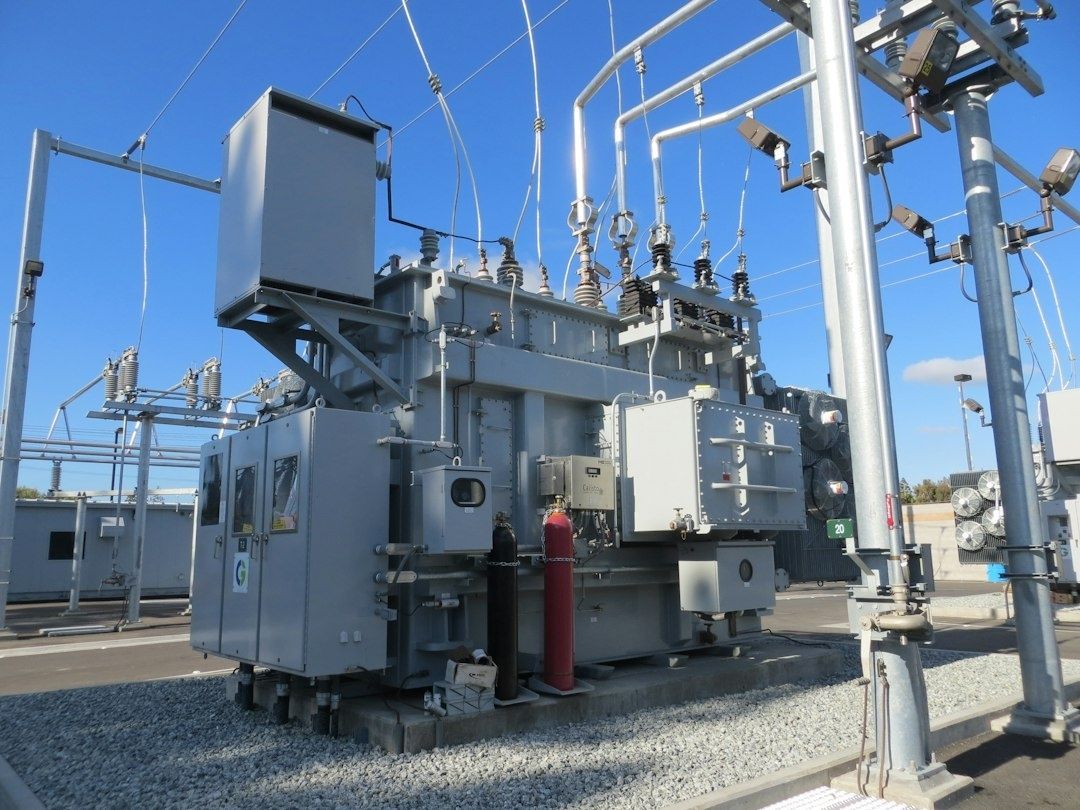
Traditional transformers remain among the most dependable components in electrical infrastructure, but their operating model was established for a largely one-directional grid. Laminated iron cores and copper windings efficiently transfer energy at 50 or 60 Hz, yet the resulting equipment is heavy, space-intensive, and comparatively inflexible. Cooling systems, insulation, protection equipment, and mechanical tap changers add further weight and maintenance requirements, particularly at substations where capacity expansion is constrained by land, noise, fire-safety, or environmental limits.
That rigidity is increasingly difficult to reconcile with modern power flows. Solar arrays and batteries can export as well as consume electricity, electric-vehicle charging introduces fast-changing demand, and data centers are creating concentrated loads that can change rapidly. A solid-state transformer, or SST, addresses these pressures by combining high-frequency isolation with power-electronic conversion. Instead of simply changing voltage, it can regulate voltage, manage power direction, support DC distribution, and respond to disturbances almost immediately. The result is a potential shift from a passive substation component to an active energy-routing hub.
The Mechanics of High-Frequency Silicon Carbide Switching
The central engineering principle is straightforward: magnetic components become smaller when they operate at much higher frequencies. A conventional transformer must process power at the utility frequency, so its core and windings need substantial magnetic material to transfer the required energy without excessive saturation or loss. An SST first converts incoming AC into a controlled DC link, switches that DC at frequencies commonly reaching the tens of kilohertz, and passes it through a much smaller high-frequency transformer. The isolated output is then converted into the voltage and waveform required by the distribution system or connected loads.
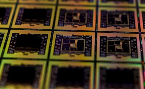
Silicon carbide, commonly abbreviated SiC, is important because the semiconductor switches must withstand high voltage, high temperature, and rapid transitions while maintaining acceptable losses. SiC MOSFETs generally offer lower switching losses and stronger high-temperature performance than many conventional silicon alternatives. Those characteristics support higher switching frequency, smaller magnetics, and more compact thermal-management systems. They do not remove engineering trade-offs: gate-driver design, electromagnetic interference, insulation coordination, parasitic inductance, cooling, and fault protection all become critical design tasks.
A practical SST is usually a multi-stage system rather than a single electronic block. Its architecture may include a medium-voltage AC to DC front end, an isolated high-frequency DC to DC stage, and a regulated DC to AC or DC output stage. Each stage requires coordinated controls and protection so that a fault in one section does not damage the others. The U.S. Department of Energy has supported this direction through transformer research, SST demonstrations, voltage-regulation projects, and silicon-carbide packaging development. Its grid resilience and silicon carbide projects also highlight advanced cooling, low-parasitic packaging, ceramic materials, and high-voltage thermal management as necessary steps toward dependable deployment.
- Front-end conversion: Active rectification controls the relationship between the medium-voltage AC network and the internal DC link.
- High-frequency isolation: A smaller transformer provides galvanic isolation while operating at a substantially higher frequency than the utility grid.
- Output regulation: Inverters and DC converters establish the voltage, frequency, power factor, and direction required by connected equipment.
- Supervisory control: Digital controls coordinate protection, thermal limits, reactive power, fault response, and communications with the wider grid.
Comparing Traditional Transformers with Solid-State Units
The most important comparison is not simply nameplate efficiency. A conventional transformer may be highly efficient at its intended operating point, but it normally requires separate equipment for rectification, voltage regulation, harmonic filtering, reactive-power support, and DC conversion. An SST can integrate several of those functions, potentially reducing total system losses and footprint even when the electronic transformer itself introduces switching losses and cooling demands. In the NC State, New York Power Authority, and EPRI demonstration, the conventional equipment being replaced was described as approximately 96% efficient, with about 4% of power lost as heat, while the SST targeted losses closer to 2% during the demonstrated operation.
Environmental and operational risks also differ. Oil-filled transformers provide effective insulation and cooling, but mineral oil can create contamination and fire concerns if a tank fails or a serious external event occurs. An SST does not require the same bulk oil inventory, although it still needs carefully engineered insulation, cooling, fire protection, arc-flash controls, and safe isolation procedures. Electronic hardware also introduces new failure modes, including semiconductor faults, control instability, sensor errors, and cybersecurity exposure. A fair evaluation must therefore include maintainability, spare-module strategy, protection coordination, and the availability of qualified service personnel.
| Characteristic | Traditional transformer | Solid-state transformer |
|---|---|---|
| Primary conversion method | Direct electromagnetic voltage transformation at 50 or 60 Hz | Power-electronic conversion with high-frequency isolation |
| Footprint and mass | Large core, windings, enclosure, and cooling system | Potentially smaller magnetics, but includes semiconductor and cooling assemblies |
| Cooling and environmental exposure | Often uses mineral oil or other dielectric fluids at larger ratings | Typically relies on electronic thermal management and solid insulation systems |
| Voltage regulation | Usually uses fixed ratios or mechanical tap changers | Can provide fast electronic regulation and power-factor control |
| Power direction | Bidirectional physics, but limited active control | Actively controls bidirectional real and reactive power flow |
| Fault behavior | Robust passive behavior with high fault energy concerns | Fast electronic blocking and isolation, with greater control complexity |
Dynamic Disturbance Isolation and Bidirectional Flow Control
An SST can function as an electrical firewall between a utility feeder and a local microgrid. Its controlled conversion stages can limit the transfer of upstream harmonics, voltage transients, and certain disturbance conditions into sensitive loads. The same interface can prevent locally generated power-quality problems from propagating back toward the utility. This does not make conventional protection unnecessary. Current-limiting behavior, bypass arrangements, isolation devices, grounding design, and selective coordination must still be engineered for the specific feeder and fault duty.
Bidirectional control is especially valuable where rooftop solar, batteries, and flexible loads operate together. A conventional transformer passes exported power back toward the feeder, but it does not independently decide how that power should be shaped or constrained. An SST can modulate current, manage reactive power, regulate a DC link, and coordinate charging or discharging. That can reduce the likelihood of local overvoltage trips when photovoltaic production is high, while also helping maintain voltage during rapid load increases. The control system must be tuned carefully, particularly on weak grids where phase-locked loops and multiport interactions can create low-frequency oscillations.
Real-world validation is now moving beyond laboratory demonstrations. In 2026, North Carolina State University, the New York Power Authority, and EPRI designed and tested a megawatt-class SST connected to a live utility distribution feeder at EPRI”s power delivery laboratory in Lenox, Massachusetts. The system handled up to 1 MW under real-world conditions. This megawatt-class utility demonstration is important because field adoption depends on more than converter efficiency. Engineers must verify protection behavior, control stability, thermal performance, communications, commissioning procedures, and interaction with existing distribution assets.
- Model the complete interface: Include the utility feeder, transformer controls, DC ports, filters, local generation, and converter-based loads in stability studies.
- Test weak-grid operation: Evaluate low short-circuit ratios, voltage disturbances, phase imbalance, and islanding transitions before energization.
- Define fault states: Establish how the SST blocks, rides through, isolates, bypasses, or restarts after internal and external faults.
- Coordinate communications: Use authenticated control channels and clear fallback modes so loss of communications does not create unsafe operating conditions.
Native DC Microgrids for Solar Batteries and High-Density AI Data Centers
Many modern energy assets are internally DC even when they connect to an AC distribution system. Photovoltaic modules produce DC, batteries store DC, and electronic loads ultimately rectify AC before using it. Electric-vehicle fast chargers also contain substantial DC conversion equipment. Routing each application through repeated AC to DC and DC to AC stages increases equipment count and creates avoidable conversion losses. An SST with a managed intermediate or output DC bus can connect these resources more directly, provided voltage levels, grounding, isolation, protection, and arc-flash requirements are addressed from the beginning.
This approach is particularly relevant to high-density computing. AI servers and accelerator clusters create steep, fast-changing power demand, while conventional data-center architectures often rely on multiple conversion stages and large UPS systems. Emerging 800 VDC architectures are intended to reduce conductor requirements, improve rack power density, and support very large computing loads. An SST can convert medium-voltage AC directly toward an 800 VDC distribution architecture while also regulating the connection to batteries, renewable generation, and utility services. However, high DC voltage presents serious arc and interruption challenges. Disconnect devices, fault detection, insulation monitoring, pre-charge circuits, and maintenance procedures must be selected for the actual DC system, not copied from an AC installation.
- Characterize the load: Document steady-state demand, step changes, short-circuit contribution, harmonic behavior, ride-through targets, and the expected growth of the computing or industrial load.
- Choose the DC architecture: Establish the medium-voltage input, intermediate DC link, distribution voltage, grounding method, isolation boundaries, and connection points for batteries and renewable resources.
- Coordinate storage and controls: Use batteries or other storage to absorb rapid load changes where appropriate, while defining limits for state of charge, ramp rate, thermal operation, and emergency shutdown.
- Prove field readiness: Complete hardware-in-the-loop studies, protection tests, thermal tests, factory acceptance testing, and staged commissioning before connecting the full facility load.
Commercial economics remain a decisive factor. SSTs generally cost more than conventional transformers because they contain semiconductors, controls, sensors, cooling systems, and specialized insulation. Their value becomes stronger when one modular platform can replace or reduce several separate systems, including voltage-regulation equipment, rectifiers, UPS capacity, and power-quality compensators. The market is also gaining urgency from data-center expansion, but through 2028 vendors still face a qualification period involving certification, manufacturing scale, field reliability, and service support. Utilities should avoid purchasing on efficiency claims alone and should require verified performance across the operating envelope.
Engineering the Resilient Grid of Tomorrow
Solid-state transformers can change the role of a substation from passive voltage conversion to active power routing. They can support bidirectional renewable flows, regulate voltage rapidly, connect native DC resources, isolate disturbances, and provide a more compact path to capacity expansion. These benefits are substantial, but they depend on disciplined engineering. Semiconductor switching does not eliminate electrical hazards, and compact equipment can concentrate heat, fault energy, and control complexity in a smaller enclosure.
A practical retrofit roadmap should begin with a detailed load-flow, fault, harmonic, thermal, and stability assessment. Next, define the required operating modes, including normal grid-connected service, battery charging, renewable export, islanded operation if applicable, black start, bypass, and controlled shutdown. Select modular equipment with documented protection behavior and accessible service paths, then validate it through staged testing on a representative feeder or microgrid. Finally, build a long-term plan for spare power modules, firmware governance, cybersecurity, technician training, and end-of-life replacement. Standardized building blocks and scaled manufacturing can reduce today”s capital premium, but the fundamentals remain unchanged: match the solution to the load, start with safety, and plan for reliable operation over the full life of the installation.